Some Note about choosing a Power Supply?
  1. In order to increase the life time of the switching power supply, we recommend users to choose a model which has rated output 25% more than actual need. For example, if a system required a power supply for 200W, we recommend the users to choose a power supply that has 250W rated power. This is to increase the life time and reliability of power supply.
  2. Please make sure the power source is 115V or 230V, if your system sell to all over the world, we recommend users choose some type with universal input(115~230V) or 115V/230V Auto sensing. It will fit all over the world.
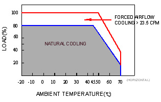
  3. To estimate the working temperature of Power Supply, and extra forced cooling equipments. When a power supply works at higher temperature environmental, it needs to lower the output power requirement. About the curve changes between the temperature ambience & rated output power load, please refer to the product specification.
  4. Read the specification of your power supply to understand all functions and the size that fit your requirement.
  5. According to your applying conditions may choose the protection function you required:
    1. Protection function: over voltage protection(OVP)、over load protection (OLP)、over current protection(OCP)、over temperature protection(OTP) , etc…
    2. Application function : signal function(POWER GOOD 、 POWER FAIL)、remote control On/Off function、remote sense function、output in parallel function , etc…
    3. Special function: power factor correction (PFC)
  6. Make sure that the model qualifies for the safety standards and EMC regulations you need.
How to choose a correct switching power supply?
  1. It’s should be noticed that the air flow of the installation position is well, whatever the power supply is natural cooling or forced cooling.
  2. When using the Class I products, make sure that the PE and ground is connecting to avoid leakage current and get an electric shock. If using Class II products that the power supply only has L,N input connecter without PE to ground, it does not need to connect to ground.
  3. The connecting wires should be shorter and the users need to notice the current range to avoid wire loss too high to lower the output voltage.
  4. If users choose the natural cooling fanless power supply and the air flow situation is bad that make internal temperature too high, it needs to add a cooling fan to assist system cooling.
Can SUNPOWER’s switching power supply be used with the source in the range of 40~440Hz? If, yes, are there any affections should be noticed?
SUNPOWER’s power supply all can be used within such frequency range. But if, the frequency is too low, the efficiency will be lower down. For example, a SPS-230P-27 under the input voltage of 230VAC and rated load, when the frequency of AC input is 50Hz, the efficiency is 86.03%, but when the frequency of AC input reduces to 40Hz, the efficiency is lower to 85.83%. And, if the frequency of AC input is too high, will reduce the value of PFC (power factor correction). Also higher frequency will cause higher leakage current too. For example, SPS-230P-27 under the input voltage of 230VAC and rated load, when the frequency of AC input is 50Hz, the leakage current is 0.58mA. When the frequency of AC input is 440Hz, the efficiency will reduce to 83.02% and the leakage current will increase to 6.1mA.
If, we need a 30V output power supply immediately, but users cannot get one right now. Can we use by two 15V power supplies, in series connecting?
Yes, that is allowed. But be aware of the rate output current of the series system being the rating of the minimum one in these series connected power supplies. In addition, we recommend users to parallel a diode at the output of power supply to prevent possible damage of internal capacitors.
If we need a 450W output power supply, can we use two units of SPS-230P-12 connected in parallel?
No, you cannot do this connection because SPS-230P-12 does not equip the parallel function. When two power supplies are connected in parallel, the one with higher output voltage will share more loading and deliver more or all power to the load. We recommend using SPS-600P-12 or SPS-1000P-12 is better option because both of them are equipped with the current share function.
When testing a triple output power supply, the +5V channel is correct, but the +12V channel and +24V channel are over the specification of this triple output power supply. What is wrong?
There are some minimum-load requirements on SUNPOWER’s multi-output (two or more output channel) power supplies generally, please refer to the specification first before connecting the load. When the electric load is 5V/6A, 12V/0A, 24V/0A, the output voltage of 12V channel and 24V channel are much higher, they are around 14.26V and 28.64V. That is over the ±6% of voltage deviation (12.72V) and ±8%(25.92V) specified in the spec. However, if we added the minimum load which are by 12V/0.2A, 24V/0.1A, the output voltage of 12V channel can be lowered down to 12.69V, and the output voltage of 24V channel can be lowered down to 25.45V. That’s matched our spec. therefore, we recommend you follow the min. load item to add min. load (dummy load ) to solve this problem, when you use multi channel type power supply.
Why cannot turn on the power supply smoothly when the loads are motors, light bulbs or other kinds of capacitive loads?
If users connect the power supply to motors, light bulbs, or high capacitive loads, which mean users required a higher output inrush current when you turn on the power supply. And such higher inrush current will cause failure of start up. We recommend that users use the power supply with constant current limiting protection to deal with these loads.
Why did the power supply shutdown during operation and after turning it off, I can restart the power supply again?
There are two possible reasons that will cause the power supply to shutdown. The first one is over load that trigger the activation of the over-load-protection (OLP). To solve this problem, we recommend choosing other type of power supply with higher output power or using some type of power supply with peak load over protection. The second one is the activation of over-temperature protection (OTP) when the internal temperature rises too high. Please check the cooling of the power supply is well. The two conditions describe will let the power supply enter protection mode and shut down. After these conditions are removed, the power supply will be back to normal.
The output ground (GND) and the ground (PE/FG) are in common at the system of our company, what recommendation we need when we use SUNPOWER’s power supply?
Yes, that is acceptable. Since our products are designed based on isolation concept between output and PE/FG, it will be all right that the output ground (GND) and frame ground (FG) is the same point in your system. But, EMI may be your notification.
During the operation of SUNPOWER’s power supply, there is some slight leakage current on the case. Is this normal? Will this leakage current hurt human body?
Due to the requirement of EMI that prevent jamming other equipments, there will be some line filters and Y capacitors between line and neutral to the FG (case). And that will cause some leakage current flow from line or neutral to the case. And this phenomenon, IEC-60950-1 requires that this current should be less than 3.5mA for IT equipment. Proper connection to earth ground is needed to solve the leakage current problem.
Because of my application condition, is that possible to reduce the noise of the fan of the power supply?
Noise is directly related to the fan, which is built into the power supply. Lowering the airflow of the fan means reducing the heat dissipation ability. It will also influence the reliability of the products. In additional, minimum airflow of fan is defined by Safety Organization and a Safety appendage will be needed, if using a new fan. Also, it is recommended when choosing a suitable power supply, fan is not necessary if wattage is under 150W. Between150~500W, both fan and fanless products are available. Above 500W, a fan is needed.
What notification is needed when installing a power supply in vertical and horizontal directions?
Most small wattage and fanless power supplies (less than 200W) are designed to install in the horizontal position. If you have to install it vertically because of system installing limitation, users should consider the output de-rating due to the heat dissipation concern. (Please refer to the spec sheet.) Concerning the power supplies with built-in fan or the application has forced cooling system, vertical and horizontal installations have less difference. For example in SPU-500 de-rating curve, the applied environmental temperature range in application is 5℃~10℃ from vertical to horizontal. The output wattage in forced cooling can be 20% higher than natural air-cooling convection.

Why the DC FAN of Sunpower’s product didn’t turn on when power supply start up?
In order to extend the life time of fan, some type of SUNPOWER’s products are operated with temperature sensing to control the fan operating. Such as SPS-350P-xx, when internal temperature under 45℃, that power supply setting up, the fan is not work. But upon internal temperature exceeded 45℃, the fan is starting to work.
Why the inrush phenomenon is happened occasionally when the power supply turns on? What should I notice?
For switching power supply, at the input side, it will have a large impluse current for about one cycle AC period <20ms. The main reason is the capacitor been charged at the moment of power supply turn on. The input voltage higher, the inrush current is bigger. This is normal condition. Because of internal protection circuit is designed, it will not damage the power supply. But we do not recommend to turning on and off the power supply continuously. Please note: simultaneously to turn on multiple power supplies, it may cause the molded-case circuit breaker turn off the entire electric system. We recommend these power supplies start up one by one or use the remote control function to turn them on/off.
Our system use SUNPOWER’s SPS-100-Q3. After turn on for a while, it will shutdown and reset occasionally. We check the current loading are under:5V/8A,12V/3.5A,-12V/0.3A,24V/1.6A (1.6A is when the motor starting up). All of these outputs are under the max. Spec. What kind of problem with this power supply?
According to your applying conditions, this system loading is up to 124W. Even each current are under the Spec. but the total output wattage is higher than limitation of 100W. We still recommend using higher output watts model on this case.
SUNPOWER’s engineer consider the demands of variety kinds of system, we have indicated the max. current for each outputs. But users still need to aware of the total output wattage, should not over the loading limit.
What is the difference between –V and GND, which are marked on the output side?
GND(GROUND) means it connect to earth ground. SUNPOWER’s products marked below:
  1. Single output:positive pole(+V),negative pole(-V)
  2. Multi output:According to channels (V1,V2,V3………), ground(GND)
  3. Isolation output:According to channel V1.G1 and V2.G2………
What’s different between AC and DC input in SUNPOWER’s catalogue?

Because of different circuit designs, power supply’s input consists of three types as below:

  1. 85~264VAC or 120~375VDC
  2. 176~264VAC or 250~375VDC
  3. 85~132VAC / 176~264VAC by Switch;250~375VDC
  1. In (a) and (b) inputs models, power supply can work properly no matter under AC or DC input. But it needs to notice that some models are designed like: positive pole connects to AC/L; negative pole connects to AC/N. And the power supply may turn on properly. If customers make a wrong connection, the power supply will not be broken. You can just reverse the input poles and power supply will still work normally.
  2. In (c) input models, please make sure that you change the 115/230V switch to 230V position and then correctly input 250~375VDC. Please be awarded if, the switch is selected on the 115V and the real input is 230V, and then the power supply will be damaged. Please be awarded.


Why the label on the power supply marked that it is 100~240VAC but the input voltage marked on the power supply spec. sheet is 88~264 VAC?
During Safety verification process, the agency will use a stricter standard ±10% (IEC60950 uses +10%, -10%) of the input voltage range labeled on the power supply to conduct the test. Therefore, operating at the wider input voltage range as specified on the datasheet is correct too. The range of input voltage labeled on the power supply is to fulfill the test standard of Safety regulation and make sure that users input correct voltage.
Will SUNPOWER’s products with CE marking meet the EMC requirements after installing into my company’s system?
We cannot guarantee it that the final system can still meet with the EMC requirements. In generally, the location, wiring and grounding installation of the switching power supply in the system may cause some different EMC characteristics. In different environment or applications, the same switching power supply may have different output results. Please refer to the users’ notification of spec. sheet.
What is the difference between Active- PFC and non-PFC model power supply?

PFC stands for Power Factor Correction. The purpose of PFC is to correct & reduce the ratio of apparent power and real power. Without PFC, the power factor has about 0.45 ~ 0.6 actual. With active PFC types, the power factor can be reached about 0.95. The description formulas are as below:

Apparent Power (VA) = Input Voltage x Input Current
Real Power (W) = Input Voltage x Input Current x Power Factor

From the users point, the Electric Power Plant needs to generate a power, which is higher than Apparent Power to the electricity users. The actual usage of electricity should be defined by real power. If the power factor is 0.5, the Power Plant needs to produce more than 200VA to a 100W real power needs. On the other way, if the power factor is 0.95, the Power Plant only needs to generate more than 105VA to provide a 100W real power needs. It will be more efficient to use electric energy. And the power source can also reduce the input current too. Meanwhile, higher power factor means can be reduced the loading of Power Plants. It can also reduce power disturbances by current harmonic wave in power supply and make higher quality of electric power to avoid damaging the facility which been connecting to power supply.

Here is a comparative table between SPS-150P-12 with active-PFC and SPS-G150-12 with non-PFC when output is 12V/12.5A below:
Model No. PFC type input(V) input(A) input(VA) input(W) PF
SPS-150P-12 Active 115 1.61 185.79 183.0 0.985
230 0.79 183.13 178.0 0.972
SPS-G150-12 --- 115 2.68 308.82 178.5 0.578
230 1.46 337.19 175.0 0.519
We use SUNPOWER’s power supply(mode: SPS-230P-05) from its terminal block through wires, and we measure the ends of the wires and it was 4.8V. However we measure on the terminal block of power supply and we got 5V. How can we solve the problem, reduce the difference?

The current coming from power supply through the wires has resistance occur. And such resistance will cause to lower potential and has potential difference. There are three way to solve this problems that we recommend users (1) reduce the length of connection wires (2) change the wires to bigger diameter (3) use SUNPOER’s power supply which has Remote Sense function, and it can higher the potential, to let the ends of wires supply 5V remainly.

For SPS-230P-05 as an example:
If we make it output 32A,connecting with 50cm wires,the wire loss are below:
AWG
Cable dia.
50cm Wire Loss
(Voltage drop)
10 0.114
12 0.184
14 0.294
Is any different between Information (EN60950-1) and Medical (EN60601-1) Safety standard?

According to the Safety standard, the leakage current in EN60950-1 Class I cannot exceed 3.5mA; in EN60601-1 the leakage current cannot exceed 300μA. The safe distance and numbers of fuse are also different when measuring.

The difference detail is below:
Subjects IEC60950-1 IEC60601-1
Creepage distance/Clearance distance Basic insulation ≧ 2.5mm / 2mm 4mm / 2.5mm
Workingvoltage:250Vrms(Max.) Supplementary insulation ≧ 5mm / 4mm 8mm / 5mm
Electric strength test Basic insulation ≧ 1500Vac 1500Vac
Supplementary insulation ≧ 3000Vac 4000Vac
Leakage current Class Ⅰ≦ Handheld type: 0.75mA -
other 3.5mA Leakage current of ground 300μA
Leakage current of case 100μA
Class Ⅱ≦ 250μA Leakage current of case 100μA
Number of fuse Class Ⅰ 1 2
  Class Ⅱ 1
Operating Temperature By manufacture defined ≧ 40 ℃
back to top